|
|
|
| |
|
| |
|
|
|
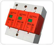
BY4 - 60 |
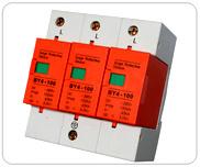
BY4 - 100 |
| |
1. Usage and application scope |
| |
BY4 type SPD is series surge protective device (protector in short) is applied in A.C 50/60 Hz , ≤380V electric power system such as TT,IT ,TN-S,TN-C and TN-C-S, and used at the equipotential connection of LPZ0A and LPZ31 zone or LPZ0B and LPZ1 zone, which protects the electric network shocked by the thunder or surge over voltage.
The protector can be made connecting with remote signaling contact, which is a normal open contact. If one or more of modular of the protector is in malfuction, the contact will be closed, and sending the malfunction signal. The rated value of remote signaling contact is AC36V,1A.
|
| |
Maximum continuous operating voltage: Uc 320, 385VAC
test classification: II grade
voltage protection level: uP< 2.0 2.5 3.0 kV
max. discharging current (8/20µs): Imax 60 80 100kA
Nominal discharge current (8/20µs): In 30 40 60kA |
| |
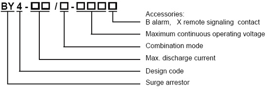
2. Model and meaning
|
| |
|
Note: combination mode: 3-3 pole combination, public pole connects to the earth.
3-3 pole combination, public pole connects to N
pole combination, public pole connects to the earth |
| |
2. Main Structure and Operating Principle
|
| |
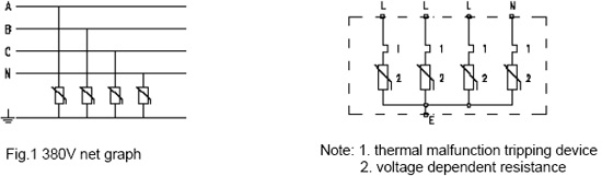
In three-phase four- line system , three phase lines and one zero line are connected protective device to the earth cable . (figure 1 ) . In normal situation , the protective device is high resistance , when the over voltage brings for electric network shocked by thunder or other reasons , the protective device will rapidly transmit in ns , then lead the voltage into earth and protect the electric equipment . As the surge voltage through the protective device and after disappear it will recover to high resistance and not influence the normal operating. |
| |
|
| |
3. Technical Parameters |
| |
Item |
BY4-60/3-385
BY4-60/3N-385
BY4-60/4-385 |
BY4-80/3-385
BY4-80/3N-385
BY4-80/4-385 |
BY4-100/3-385
BY4-100/3N-385
BY4-100/4-385 |
Maximum continuous operating voltage Uc |
385 V |
Test grade |
Class 2 |
Nominal discharge current In(8/20µs) |
30kV |
40kV |
60kV |
Maximum discharge current Imax (8/20µs) kA |
60kV |
80kV |
100kV |
Voltage protective level Up |
2.0 kV |
2.5 kV |
3.0 kV |
Response time ns |
< 25 ns
|
Defending grade |
IP20
|
Ambient temperature |
-40---- +85ºC |
Color ( Mould ) |
Orange |
( Base ) |
Grey |
Outer covering material |
Reinforced fire-retardant nylon PBT |
Phase Line , Zero Line |
6 ----3 5mm2 |
Earth Line |
6 ----3 5mm2 |
Signal Line |
1.5 mm2 |
Accessory |
According to the needs adding the remote signaling contact |
|
| |
Item |
BY4-60/3-320
BY4-60/3N-320
BY4-60/4-320 |
BY4-80/3-320
BY4-80/3N-320
BY4-80/4-320 |
BY4-100/3-320
BY4-100/3N-320
BY4-100/4-320 |
Maximum continuous operating voltage Uc |
320 V |
Test grade |
Class 2 |
Nominal discharge current In(8/20µs) |
30kV |
40kV |
60kV |
Maximum discharge current Imax (8/20µs) |
60kV |
80kV |
100kV |
Voltage protective level Up |
2.0 kV |
2.0 kV |
2.5 kV |
Response time ns |
< 25 ns
|
Defending grade |
IP20
|
Ambient temperature |
-40---- +85ºC |
Color ( Mould ) |
Orange |
( Base ) |
Grey |
Outer covering material |
Reinforced fire-retardant nylon PBT |
Phase Line , Zero Line |
6 ----3 5mm2 |
Earth Line |
6 ----3 5mm2 |
Signal Line |
1.5 mm2 |
Accessory |
According to the needs adding the remote signaling contact |
|
| |
4. Installation position and application |
| |
1. SPD class B, functioning as an equi-potential connection in case of lightning.
2. Installed at the joint of the LPZOA, LZPOB and LPZ1 zones.
3. It is usually installed in low voltage main distribution cabinet connected to the incoming end of the buildings.
4. It adopts 35 mm DIN rail.
5. It is linked by 6 --- 35 mm2 copper wire
6. The cable should choose double color wire which is longer than 6 mm2
7.. In order to guarantee electrical network's normal operating after protective device losing efficiency , the protective device which linked to the phase line must be connected a fuse box whose current is higher than 63A or a circuit breaker. |
| |
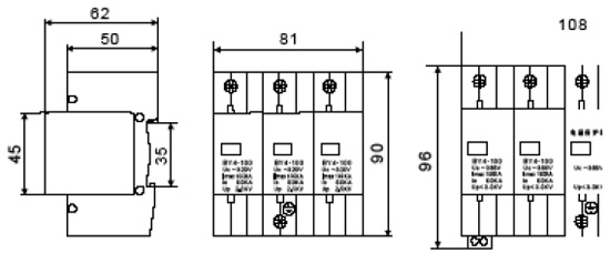
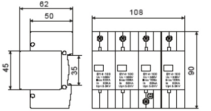
5. Appearance and Installation Dimension |
| |
|
| |
|
| |
|